How to build an XOR gate using NAND gates

We can build a 2-input XOR gate using 5 NAND gates. Sound interesting, isn't it? Let us see how.

As we know, the logical equation of a 2-input XOR gate is given as below:
                      Y = A (xor) B = (A' B    +    A B')
Let us take an approach where we consider A and A' as different variables for now (optimizations related to this, if any, will consider later). Thus, the logic equation, now, becomes:
                       Y = (CB    +    A D)           -----   (i)
     where
                      C = A'     and      D = B'
De-Morgan's law states that

                                m + n = (m'n')'

Taking this into account,
                     Y = ((CB)'(AD)')' = ((A' B)'  (A B')')'
Thus, Y is equal to ((A' nand B) nand (A nand B')). No further optimizations to the logic seem possible to this logic. Figure 1 below shows the implementation of XOR gate using 2-input NAND gates.
A 2-input XOR gate can be implemented as shown in figure.
Figure 1: 2-input XOR gate implementation using 2-input NAND gate
Thus, we have seen an XOR gate can be implemented by putting NAND gates in cascade. Can you think of a better way of implementing XOR gate using NAND gates?


Also read:

STA problem: Maximum frequency of operation of a timing path

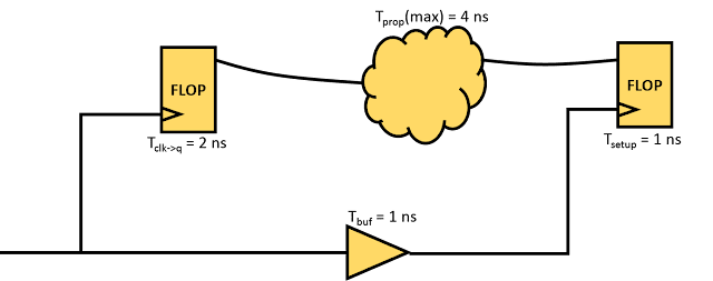
Problem: Figure 1 below shows a timing path from a positive edge-triggered register to a positive edge-triggered register. Can you figure out the maximum frequency of operation for this path?
find out the maximum frequency of operation for path shown
Figure 1: A sample timing path
Solution:
The above timing path is a single cycle timing path. The maximum frequency is governed by setup timing equation. In other words, maximum frequency of operation is the maximum frequency (minimum time period of clock) that satisfies the following condition:

 Tck->q + Tprop + Tsetup - Tskew < Tperiod
Here,
 Tck->q = 2 ns, Tprop = 4 ns, Tsetup = 1 ns, Tskew = 1 ns, Tperiod 
Now,
Tperiod > 2 ns + 4 ns + 1 ns - 1 ns
Tperiod > 6 ns
So, the minimum time period of the clock required is 6 ns. And the maximum frequency that the above circuit can work is (1000/6) MHz = 166.67 MHz.

It should be noted that at if we operate this timing path at maximum frequency calculated, setup slack will be zero. :-)

In this post, we talked about frequency of operation of single cycle timing paths. Can you figure out maximum frequency of operation for half cycle timing paths? Also, there is a relation of maximum operating frequency to hold timing? Can you think about this situation?

Also read: