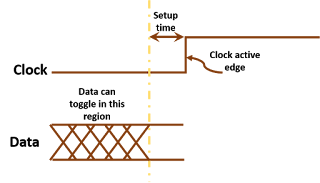
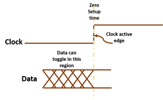
As we know from the definition of setup time, setup time is a point on time axis which restrains data from changing after it. Data can change only before occurrence of setup timing point. Theoretically, there is no constraint on occurrence of setup time point with respect to clock active edge. It can either be before, after or at the same time as that of clock edge. Depending upon the relative occurrence of setup time point and clock active edge, setup time is said to be positive, zero or negative.
Positive setup time: When setup time point is before the arrival of clock edge, setup time is said to be positive. Figure 1 below shows positive setup time.
 |
| Figure 1: Positive setup time |
Zero setup time: When setup time point is at the same instant as clock's active edge, setup time is said to be zero. Figure 2 shows a situation wherein setup time is zero.
 |
| Figure 2: Zero setup time |
Negative setup time: When setup time point occurs after clock edge, setup time is said to be negative. Figure 3 shows timing waveform for negative setup time.
 |
| Figure 3: Negative setup time |
What causes different values of setup time: We have discussed above theoretical aspects of positive, zero and negative setup time. Let us go a bit deeper into the details. Figure 4 shows a positive level-sensitive D-latch. As we know from the definition of setup time, setup time depends upon the relative arrival times of data and clock at input transmission gate (We have to ensure data has reached upto NodeD when clock reaches input transmission gate). Depending upon the relative arrival times of data and clock, setup time can be positive, zero or negative.
 |
| Figure 4: Positive level-sensitive latch |
Now, if data takes 1 ns more than clock to reach input transmission gate from the reference point, then, data has to reach reference point at least 3 ns before clock reference point. In this case, setup time will be 3 ns.
Similarly, if data takes 1 ns less than clock to reach input transmission gate, setup time will be 1 ns. And if data takes 2 ns less than clock to reach input transmission gate, setup time will be zero.
Now, if there is further difference between delays of data and clock from respective reference points to input transmission gate, the hold time will become negative. For example, if data takes 3 ns less than clock to reach input transmission gate, setup time will be -1 ns.
This is how setup time depends upon relative delays of data and clock within the sequential element. And it completely makes sense to have negative setup time.
Also read:
Also read:
So it is kind of like propagation delay meeting or not meeting before the positive level of Latch 1, right?
ReplyDeleteYes, kind of. Better be called delay difference.
DeleteOne more point i would like to add. The input reference point that you are talking about the d pin and the clock pin of the flip flop. Now if the delay through the data path to latch point is shorter than the clock path to latch point , the data can arrive late at the D pin(common reference point) wrt clock at clock pin and still get captured effectively by the flip flop.So when we see wrt to the reference point it would correspond to a negative or zero setup time
ReplyDeleteIs there any violation of setup in three cases. If not any violation why?
ReplyDeleteHi there could be or there could not be a violation.
DeleteBasically, violation depends upon expected and actual relationship between clock and data signals.
In this post, we have talked only about the actual relationship. Whether there is a violation or not will depend upon expected relationship as well.
Hope this clarifies.